Base plates and anchors
What you define#
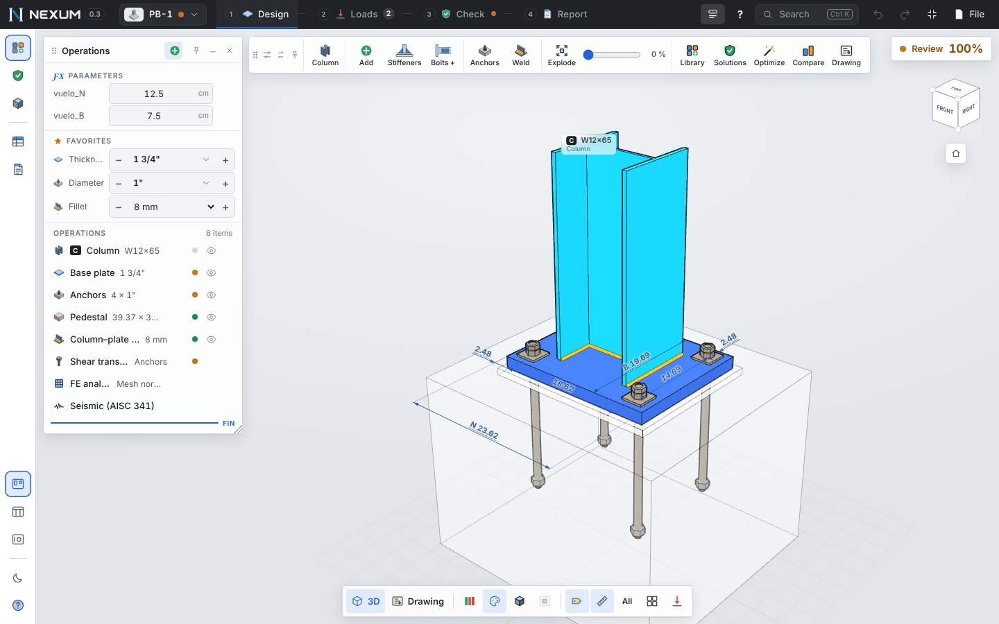
- Column — W or HSS, steel.
- Plate — N × B, thickness (inches), steel; the plate and pedestal follow the column by default (ƒ).
- Anchors — type, diameter, grade, embedment hef, layout. Lines × anchors per side, a perimeter ring, or a custom layout drawn in the bolt editor.
- Pedestal and concrete — dimensions, f′c, grout thickness, cracked concrete (always, ψc = 1.0).
- Shear transfer — friction, the anchors, or a shear lug (embedded plate under the base plate).
- Ribs — on any face (+x, −x, +z, −z), number per face, gap and offset. Nexum places them over column metal, clear of nuts and wrench clearance, with room to weld; ribs that do not fit are left out and the reason is given.
Analytical method#
AISC Design Guide 1 (3rd ed.)
- Concrete bearing φ·0.85·f′c·√(A2/A1) ≤ φ·1.7·f′c, with A2 geometrically similar and concentric.
- Axial load, small eccentricity (e ≤ e_crit) and large eccentricity (anchors in tension), with the exact DG1 Eq. 4-58 for one tension line, a rigid plate for several lines, the elastic Eq. 4-67, and biaxial bending (Eq. 4-69).
- Plate thickness from the cantilevers m, n and λn′ on the compression side and from the anchor line on the tension side.
- Column-to-plate weld (J2.4). With ribs, the column weld and the ribs are checked as one elastic weld group (Blodgett §7.4) — never stronger than without ribs — plus the rib-to-column fillet and the rib as a bracket.
ACI 318-19 Chapter 17 for the anchors, by groups as IDEA StatiCa does: overlapping cones, the exact projected area ANc, ψec on each axis.
| Check | Clause |
|---|---|
| Steel in tension and shear (×0.8 with grout) | §17.6.1, §17.7.1 |
| Concrete breakout in tension (group, ψed, reduced hef with three near edges) | §17.6.2 |
| Pullout | §17.6.3 |
| Side-face blowout | §17.6.4 |
| Bond (adhesive anchors) | §17.6.5 |
| Concrete breakout in shear toward the pedestal edge | §17.7.2 |
| Pryout | §17.7.3 |
| Tension–shear interaction (exponent 5/3) | §17.8 |
| Shear lug: bearing φ·1.7·f′c·A_ef, breakout, lug bending and weld | §17.11 |
When concrete breakout still fails, ACI §17.5.2.1 allows anchor reinforcement instead; Nexum flags it but does not design it.
Anchor types#
| Type | Family | Pullout / bond | Notes |
|---|---|---|---|
| Rod with heavy hex nut | Cast-in | Np = 8·Abrg·f′c (§17.6.3.2.2a) | Default |
| Rod with nut and anchor plate | Cast-in | Np = 8·Abrg·f′c, Abrg = side² − πd²/4 | Plate size editable; warning if thinner than its overhang |
| Headed stud (Nelson H4L) | Cast-in | Np with the catalog head (5/8"–1") | Ase of the unthreaded shank; AWS D1.1 Type B |
| L and J hook | Cast-in | Np = 0.9·f′c·eh·da (§17.6.3.2.2b) | No side-face blowout; AISC advises against hooks in tension |
| U anchor | Cast-in | Each leg as a hook with eh = s/2 | Nexum's criterion: ACI 318 has no U type |
| Adhesive | Post-installed | Bond, Nba = τcr·π·da·hef | τcr, τuncr, kc and category are manufacturer data (ESR, ACI 355.4) |
| Expansion (torque-controlled) | Post-installed | Np,cr from the ESR | φ by category |
| Undercut | Post-installed | Np,cr from the ESR | ESR often gives kc = 24 |
All checks, the FE and CBFEM models, the anchor table, the 3D model, the drawing (with an anchor sheet showing hef, eh, the plate or head) and fabrication come from the same anchor definition.
CBFEM model#
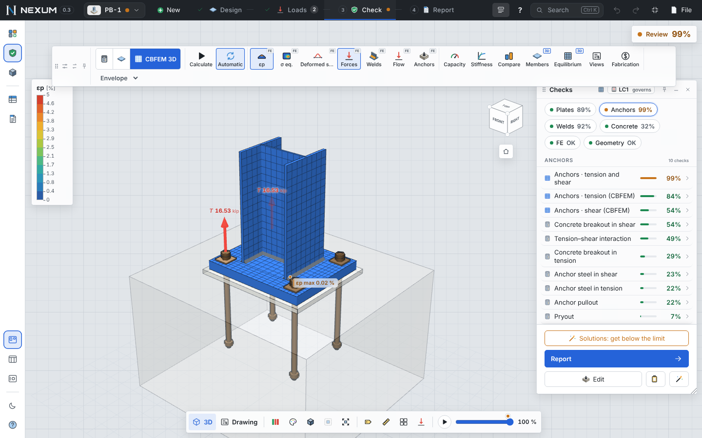
In CBFEM the plate, column and ribs are shells; anchors are springs with the IDEA StatiCa curve up to φNsa (tension only, length = ½ nut + washer + plate + grout + 8d); the concrete is a compression-only support with IDEA's subsoil stiffness.
- Plate: plastic strain ≤ 5%.
- Anchors: the tension of each anchor from the model, checked with ACI 318 Ch. 17 by groups.
- Concrete bearing: the effective area A1 is where the stress is ≥ a cutoff × peak (IDEA with AISC: 0.1, editable) less the holes; A2 similar and concentric (1V:2H pyramid); average stress in A1 against φc·0.85·f′c·√(A2/A1) ≤ φc·1.7·f′c.
- Friction shear: φ·μ·C with C from the contact map.
Why DG1 and CBFEM differ#
DG1 assumes the concrete at its maximum stress in a block against the plate edge — the longest possible lever arm, a plastic lower bound. CBFEM, like IDEA StatiCa, spreads the compression elastically under the plate and close to the column, so the arm is shorter and the anchors take more tension. As the load approaches the strength both converge. For thin plates the FE value is the representative one; a thicker plate brings both closer. The Compare tool shows the two side by side with this explanation.