Designing a connection
Members#
Members come first in Operations, with the same tag they carry in the model: C column, B1 beam, G girder, D1 brace, T chord. Click one to change its shape, steel and position (angle, offset, eccentricity).
Shape selector. Type W14x90, 14 90, HSS 6, L4x4 or A572 and the list filters at once. Each option shows its key properties (depth, flange width, thickness, weight, or Fy/Fu for steels), grouped by family (W by depth, square and rectangular HSS, round HSS and pipe, angles, channels, tees), with your recent picks on top. Keyboard: ↑ ↓, Enter, Esc. Metric designations (IR, PTR, LI) are an option.
Operations#
Each operation is one part of the connection: a plate, a group of bolts, a weld, a stiffener. Its line in the tree shows the key value, a warning badge ⚠ when it has notes (click it for the notes and their fix), a status dot, and an eye to hide it. Optional operations (continuity plates, doubler plate, shear lug…) can be suppressed with the eye without deleting them.
The here marker can be dragged (or moved with ↑ ↓) to see the model up to that operation, like a CAD history.
The operation panel#
Clicking an operation turns Operations into its edit panel:
- Compact properties — each value on one row; drag sideways over the number or its label to change it live (8 px = one step, Shift = fine), or use the − / + that appear on hover. Each drag is a single undo step.
- Pictograms next to each label (t, n, Ø, a, s, g, edges, angle, material, force) and drawn tiles for short choices (support type, welded or bolted, thread condition N/X, hole type, 4E or flush, contact).
- Material (steels, electrode, bolt grade) sits in a collapsible section at the end.
- Live effect — how the governing check changes as you edit (analytical).
- ✓ / Enter accepts; ✕ / Esc cancels and reverts everything changed during the edit, including pinned panels.
Pin. 📌 in the panel header, Pin in the selected piece bar, or Shift+click in the tree keeps that operation's data open under the tree, so you can edit several pieces at once.
Smart limits#
Numbers have limits that come from the code and from the geometry: bolt spacing and edges (J3.3–J3.5), wrench clearance (Manual Table 7-15), the room available on the member. They narrow the range of the field and are shown under it. Fillet sizes mark their J2.4 minimum and J2.2b maximum.
Shop rounding#
Plate dimensions round to shop multiples: Auto (≥ 30 cm closes at 5 cm, smaller at 0.5 cm — in inches, 1" and ¼"), or a fixed 1 / 2.5 / 5 cm. Change it in File → Shop preferences.
Parametric values (ƒ)#
New connections follow their members: rows of bolts from the beam depth, plate width from the flange, base plate and pedestal from the column, the shear tab fillet at 5/8·tp. Those values show a small ƒ. If you type a different value it stops being automatic (Nexum tells you) and ↺ brings it back.
In developer mode (File → Developer mode) the ƒx editor lets you write your own parameters with expressions, links to any value and rules — like the parametric templates of IDEA StatiCa.
Bolt editor#
Open it from the Bolts operation, the bolts icon, or the halo. The layout is drawn on the plate in the 3D model:
- outline, minimum edges, forbidden zones and wrench clearance;
- dimensions in place — click one to change it: in General mode they change pitch, gage or center; in Custom they move the bolts on the other side, the whole group, or away from a forbidden zone;
- a coordinate table like IDEA's, a snap toggle and the bolt data (grade, diameter, threads, hole type, pretension);
- a single serious warning next to its bolt; the rest folded in one line.
N switches between the normal view and 3D. Enter / Esc / ✓ close it and the camera returns.
Welds#
Each weld operation has its type (fillet or CJP, depending on the joint), size in mm (3, 4, 5, 6, 8, 10, 12, 14, 16), electrode and, where it applies, one or both faces. Its row marks the J2.4 minimum.
Size welds automatically: in a weld's panel, Adjust fillets picks the smallest allowed fillet that passes, either by force or at full strength of the welded element (5/8·t for ductile behavior is also available).
Joints: welded or bolted#
Several interfaces can be switched between welded and bolted with one click; Nexum adds the pieces each joint needs and checks them:
| Connection | Interface | Welded | Bolted |
|---|---|---|---|
| Shear tab | Support | Plate welded to the support | Tee bolted to the support |
| Shear tab | Beam web | Plate bolted to the web | C-shaped fillet to the web |
| Double angle | Support / web | Angle legs welded (tip and returns) | Bolted legs |
| Gusset plate | Support | Plate welded | Two clip angles bolted |
| Gusset plate | HSS brace | Slotted tube welded to the plate | Knife plate welded in the slot, bolted to the gusset |
Added pieces#
The + of Operations has two sections: Operations (the optional ones of the template) and Pieces, which can be added to any connection without changing its template:
| Piece | Templates | Smart placement |
|---|---|---|
| Seat / top angle | Shear tab, double angle | Length = beam bf rounded to 5 cm, trimmed to the support; gage between the wrench clearance and the J3.4 edge; bolted or welded to the support |
| Cover plate on flange | Shear tab, end plate, double angle | Width bf − 2·(fillet + ⅛″); starts after the flange weld and the nuts; fillet 5/8·t |
| Column stiffeners | Shear tab and double angle to the flange | At the beam flanges, full flange width, t ≥ tf/2 (J10.8) |
| Web stiffeners | Shear tab, end plate, double angle | Pair on both sides of the web, outside the connection |
| Ribs | Base plate | In the web plane, column to plate edge; corner clip clears the column weld; split in two if an anchor sits on the axis |
| Support stiffeners | Gusset plate | In the support web under the plate ends |
| Free plate | All | On the face you choose |
Each piece keeps what you ask and fits itself to the connection: change the beam and it trims or moves. It is checked for clashes against the template and the other pieces (a clash is Fail · Clash, not a percentage, and the piece turns red). With the CBFEM engine the pieces enter the model as shells, welded where they touch, with contact and bolts.
Change the connection type#
Right-click a member → Connect to…, or the connection selector → Templates for this joint: Nexum proposes the templates that fit the beam and support, with their estimated utilization for the same loads. Applying one keeps the members, steels, name and load cases.
Optimize#
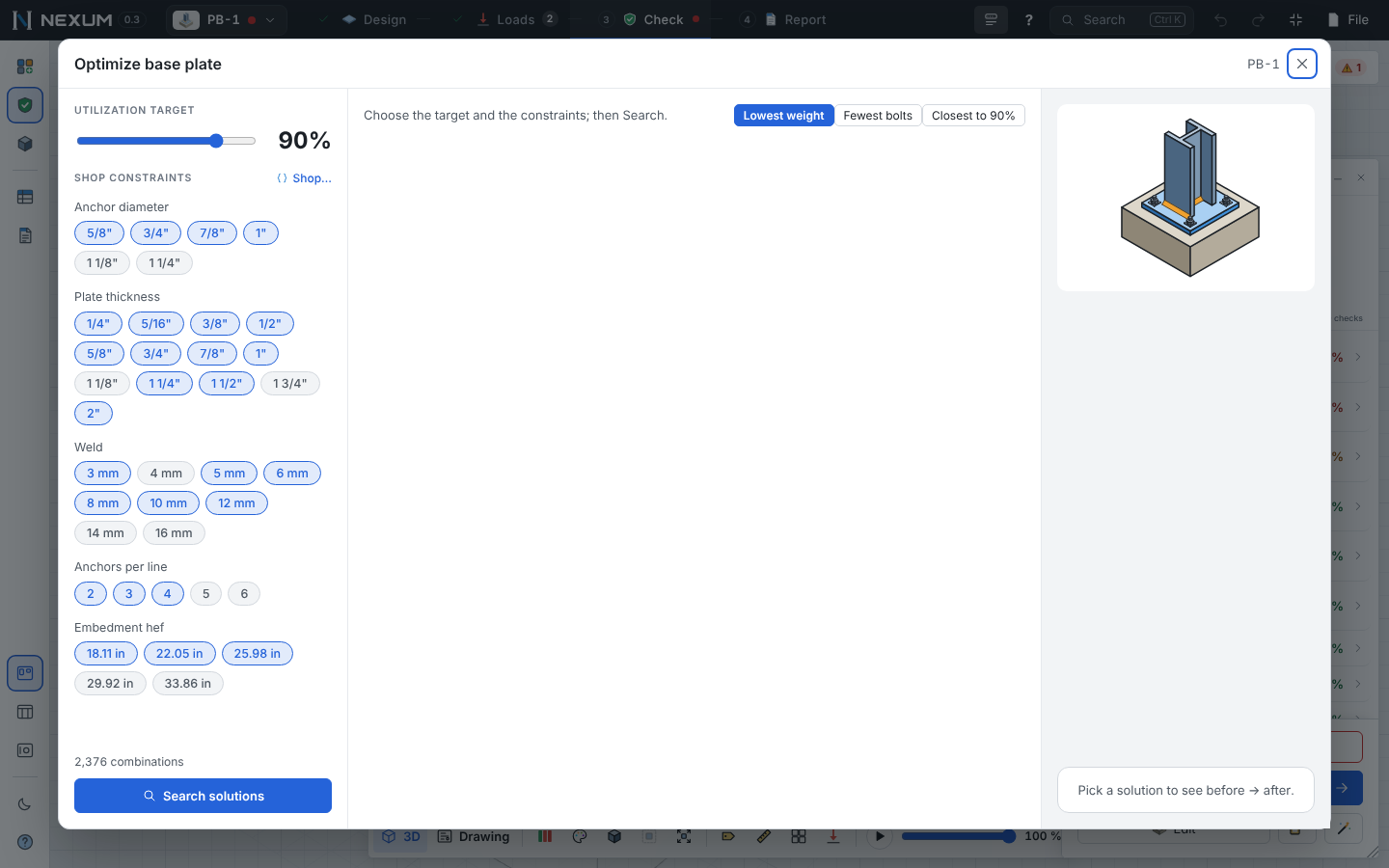
Optimize (toolbar, or the wand) with a target utilization (for example 90%) and constraints as chips (diameter, thickness, fillet, bolts per line, embedment…). Nexum checks every combination with the analytical method in the background and lists those that pass, sorted by lowest weight, fewest bolts or closest to the target, with before → after (%, kg). Apply (or double-click) changes the data. Your shop preferences (diameters, thicknesses and fillets your shop works with) limit the search.