CBFEM analysis
CBFEM — the component-based finite element method — models the connection as a set of components: the plates and member walls as nonlinear shells, and the welds, bolts, anchors, contact and concrete as components with their own stiffness and strength. The plates are judged by plastic strain; the components by the code checks with the forces the model finds. It is the same idea as IDEA StatiCa's, and Nexum follows its published theoretical background wherever it applies to AISC.
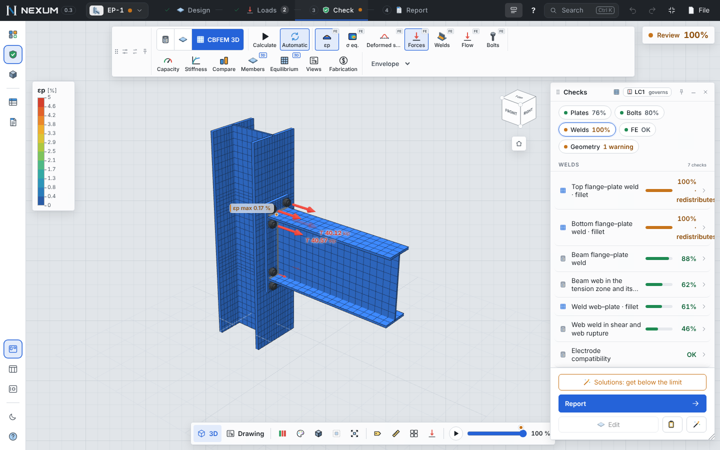
The model#
| Part | How it is modeled |
|---|---|
| Plates and member walls | 4-node shells: membrane with Allman drilling rotation, MITC4 bending, 5 integration layers through the thickness (Simpson; Gauss–Lobatto as an option) |
| Steel | Bilinear von Mises, design yield φ·Fy (φ = 0.9, LRFD), hardening E/1000, exact return mapping with consistent tangent |
| Members | Segments of 2 depths from the joint, loaded at their free end; the far member end is supported |
| Welds | Throat elements joined by constraints, with directional strength; double fillets with one element per face |
| Bolts | Shear stiffness k11/k12 up to 0.999·φRnv; tension curve c1/c2 up to φRnt (as IDEA StatiCa); a rigid spider to the hole |
| Holes | Bolt holes meshed with 1–3 rings (16 elements around in plates, 8 in member walls), standard hole size J3.3 — like IDEA 24.1 |
| Contact | Plate-to-plate, compression only, by penalty |
| Concrete | Compression-only support with IDEA's subsoil stiffness; anchors as tension-only springs |
| Solution | Incremental Newton–Raphson (modified Newton by default, full Newton as an option) with automatic step cutting |
The model stops before 100% of the load if the plastic strain passes 15% (a plastic mechanism) or the solution cannot converge; then the Nonlinear analysis check fails and the connection does not pass.
Checks from the model#
| Component | Check |
|---|---|
| Plates | Equivalent plastic strain εp ≤ 5% (reported as a percentage of the limit) |
| Welds | Most stressed element of each weld against φRn (J2.4), plastic redistribution allowed up to the limit |
| Bolts | Each bolt in the direction of its own force: shear, tension with prying, J3.7 interaction, bearing and tearout (J3.10) |
| Anchors | ACI 318 Ch. 17 by groups with the model forces |
| Concrete | Bearing (J8) on the effective contact area |
| Buckling | Linear buckling factor αcr against the IDEA limits for AISC |
Rupture of net sections and block shear are not seen by a von Mises shell model; they stay as analytical checks next to the CBFEM ones.
Calculation settings#
File → Calculation settings… (applies to the whole project; only the values you change are stored; export and import as .json):
| Setting | Default |
|---|---|
| Plastic strain limit | 5% |
| Stop the analysis if εp exceeds | 15% |
| Bearing area cutoff (concrete) | 0.1 × peak |
| Steel resistance factor φ | 0.90 |
| Hardening | E/1000 |
| Elements per section depth / on plates | by mesh density |
| Minimum / maximum element size | mm |
| Member segment length | 2 depths |
| Bolt holes | With rings (recommended) or without hole (≈ 30–45% faster) |
| Integration through the thickness | Simpson, 5 layers |
| Initial load increments, tolerance, max. iterations | 10⁻⁵ force tolerance |
| Tangent | Modified Newton (recommended) or full Newton |
Buckling#
Linear buckling (αcr) in the Check toolbar computes 6 modes on the governing case. Limits used by IDEA StatiCa with AISC: connection plates αcr ≥ π²E/(625·Fy) (KL/r = 25 of J4.4), member plates ≥ 3, brackets and stiffeners ≥ 4. Below the limit, check that plate's buckling by the code or increase its thickness.
Stiffness and design resistance#
With the CBFEM engine, Stiffness computes the M–φ curve including the column flexibility and classifies the joint (AISC 360 Commentary B3.4b), and Capacity finds the load factor at which the first component reaches its limit.
Equilibrium#
Members and equilibrium lists the model type of each member, the net force at each end and the global sum, which must be zero. It is a quick way to confirm that the loads you entered are in equilibrium the way you expect: what does not balance is taken by the support member.
Verification#
The solver is tested against closed-form solutions (Timoshenko plates and beams, patch tests, plasticity in uniaxial tension, a cantilever reaching its plastic load, mesh convergence) and against IDEA StatiCa's published studies for the shear tab and the base plate. See Verification.