Your first connection, step by step
This walkthrough designs a bolted extended end plate (4E) moment connection of a W18×50 beam to the flange of a W14×109 column, for two factored load cases. It takes about ten minutes and covers every stage you will use in any other connection type.
Step 1 — Create the connection#
Press + New in the top bar (or Alt+N). The New connection window has four columns, left to right:
- Class — column base, beam to column, column with beams, beam to girder, splice, truss, portal frame, crane, plates on HSS, hanger, bracing, member, from scratch, my templates.
- Geometry — for beam to column: to the flange, to the web, over an HSS column.
- Design — shear tab, double angle, shear end plate, end plate (moment), flange plates, welded moment…
- Parameters — the key shapes and the first load case.
Choose Beam to column → To the flange → End plate (moment), set the beam to W18×50 and the column to W14×109, and press Enter (or double-click the design tile).
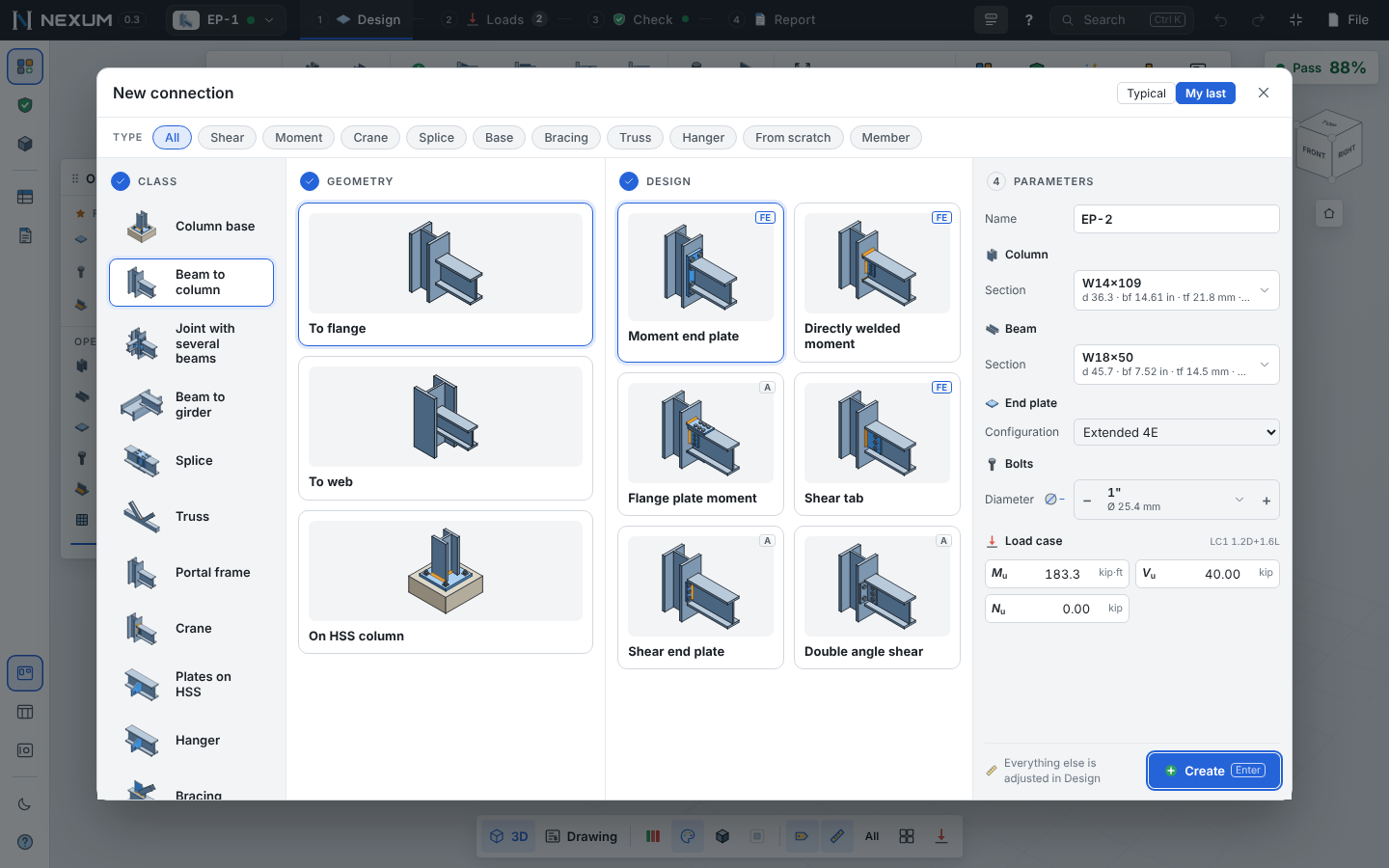
Everything has a value from the start: plate, bolts and welds follow the shapes (rows of bolts from the beam depth, plate width from the flange width, fillet from the plate thickness). Those automatic values carry a small ƒ next to their label. My last starts from the last connection of that design you made; Typical from the example.
Step 2 — Design#
The Operations window lists the connection like a history: the members first (column C, beam B1), then each operation (end plate, bolts, welds, FE analysis), each with its key value on the same line and a colored dot with its status.
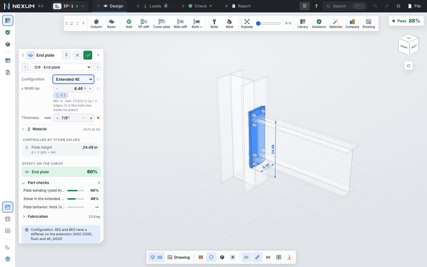
Edit the plate. Click End plate. The window turns into the operation panel:
- one row per value — label on the left, value on the right; drag left or right over a number to change it live (Shift = fine), or use − / +;
- the dashed outline in the model shows how it was before;
- the live effect line shows how the governing check moves (for example 95% → 81%), computed with the analytical method as you type;
- ✓ / Enter accepts, ✕ / Esc puts everything back.
When the design looks right, press Next: Loads at the bottom of Operations. Use Alt+↑ / Alt+↓ (or the arrows in the breadcrumb ‹ 3/8 · Plate ›) to step to the previous or next operation without closing the panel.
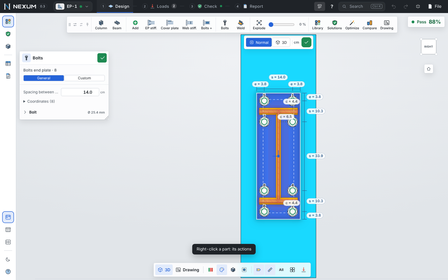
Edit the bolts. Click Bolts, or the bolts icon in the toolbar. The bolt editor draws the bolt layout right on the plate in the 3D model, in a view normal to the plate: outline, minimum edges, forbidden zones (flanges, web, welds, wrench clearance), dimensions and numbered bolts. Click any dimension to change the pitch, gage or edge; switch to Custom to move individual bolts or type their coordinates. N toggles between the normal view and 3D. Enter closes the editor and the camera returns.
Favorites. The three values you change most (plate thickness, bolt diameter, fillet size) sit at the top of Operations. The ★ next to any value adds or removes it.
Add pieces. The + of Operations opens the gallery: optional operations of the template (stiffener on the extension, continuity plates, web doubler plate) and free pieces (seat angle, cover plate, column stiffeners, web stiffeners, plate on any face). Pieces that do not apply are grayed out with the reason. See Designing a connection.
Step 3 — Loads#
Click Loads (Alt+2). The load table opens in the Tools window and the arrows of each force appear on the model.
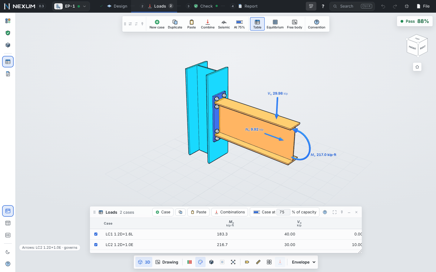
- Each row is a factored (LRFD) load case: name, then the forces of this connection type (for an end plate: Mu, Vu, Nu).
- Work in it like a spreadsheet: Tab, Enter, arrow keys. Paste a block copied from Excel.
- The checkbox of each row includes or excludes the case from the calculation (at least one stays on).
- ? in the table header shows the sign convention with a figure.
- A ⚠ next to a value means the analytical method ignores that force (it is still checked by the FE model).
The example uses these two cases:
| Case | Mu (kip·ft) | Vu (kip) | Nu (kip) |
|---|---|---|---|
| LC1 1.2D+1.6L | 183.3 | 40.0 | 0 |
| LC2 1.2D+1.0E | 216.7 | 30.0 | 10.0 |
When the cases are in, press Next: Check at the bottom of the table.
Step 4 — Check#
Click Check (Alt+3). The analytical checks are already done — until now the status widget said analytical next to the verdict — the FE model runs by itself in the background (the status widget shows its progress; F5 runs it on demand).
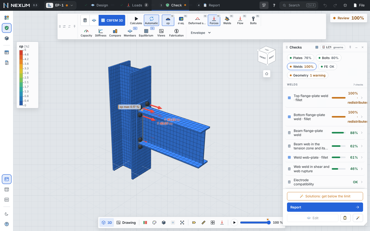
The Checks window reads top to bottom:
- What happens — Pass, Review or Fail, with its color, then the governing utilization, check and load case.
- Group chips — Plates, Bolts, Welds, Column, Geometry… Click one to filter the list and highlight its pieces in 3D.
- The list — what · bar · % for every check of the group.
- The detail — open a check to see the code clause, the formula, the substitution with your numbers, the result and the case that governs. Step by step numbers each step; Assumptions lists what the method takes for granted; To lower it says what to change.
For the end plate, the checks follow AISC Design Guide 39 (4E and flush) or Design Guide 4 (4ES and 8ES): plate bending by yield lines, bolt tension with or without prying, bolt shear and bearing, shear of the extended part, flange and web welds; and on the column: flange bending, web local yielding and crippling, panel zone shear, and continuity plates when you add them.
When something fails, the main button at the bottom of the Checks window becomes Solutions (the report is still one click below): Nexum tries small changes alone and combined (thicker plate, larger bolts, more rows, a 4ES stiffener, continuity plates, a doubler plate), sorts them by cost, and confirms the best three with the FE model before calling any of them passes. Hover a solution to preview it dashed in 3D; Apply changes the data (Ctrl+Z undoes it).
Look at the FE results. In the toolbar choose Plastic strain, Stress or Deformed shape; the legend shows the bands with the 5% limit marked. Elements opens a split view with the table of every plate and wall (thickness, stress, plastic strain) and the selected element in 2D with its mesh and bolts.
Step 5 — Report and drawings#
Click Report (Alt+4).
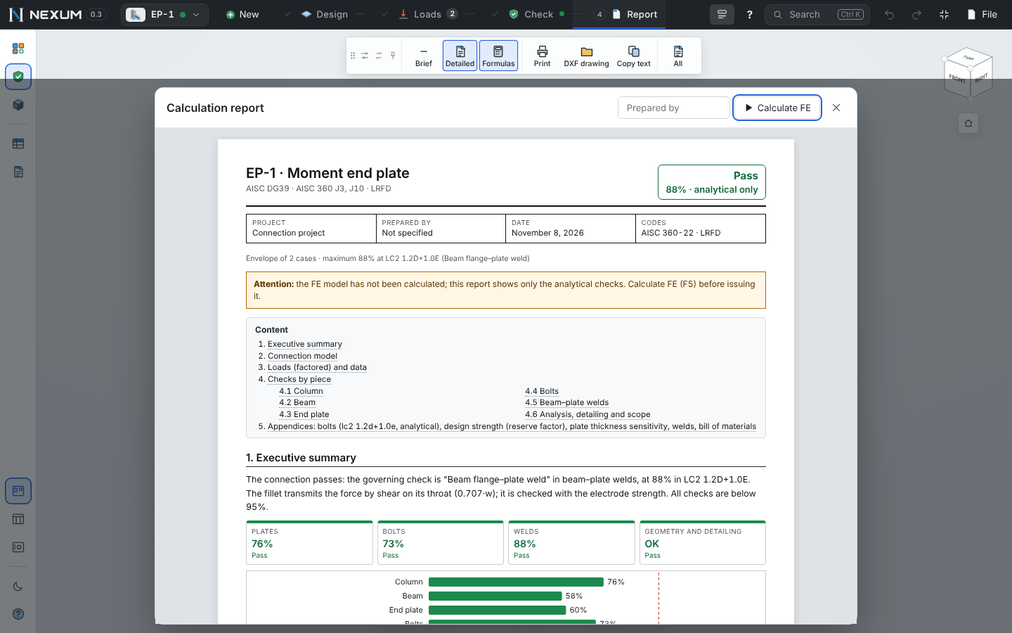
The report opens with a table of contents, an executive summary (verdict, what governs, which piece, which case and the failure mechanism), a utilization chart by piece, and then:
- Executive summary
- Connection model (members and pieces, load path, method, assumptions, detail drawing)
- Loads (factored) and data
- Checks by piece — each piece with its own figure and, for each check, the failure mechanism in one line followed by symbol = formula = substitution = result
- Analytical vs. finite elements (when the FE ran)
- Appendices: bolts, design strength (reserve factor), plate thickness sensitivity, welds (AWS A2.4 symbols), bill of materials
Print / PDF prints it on letter-size pages with page numbers.
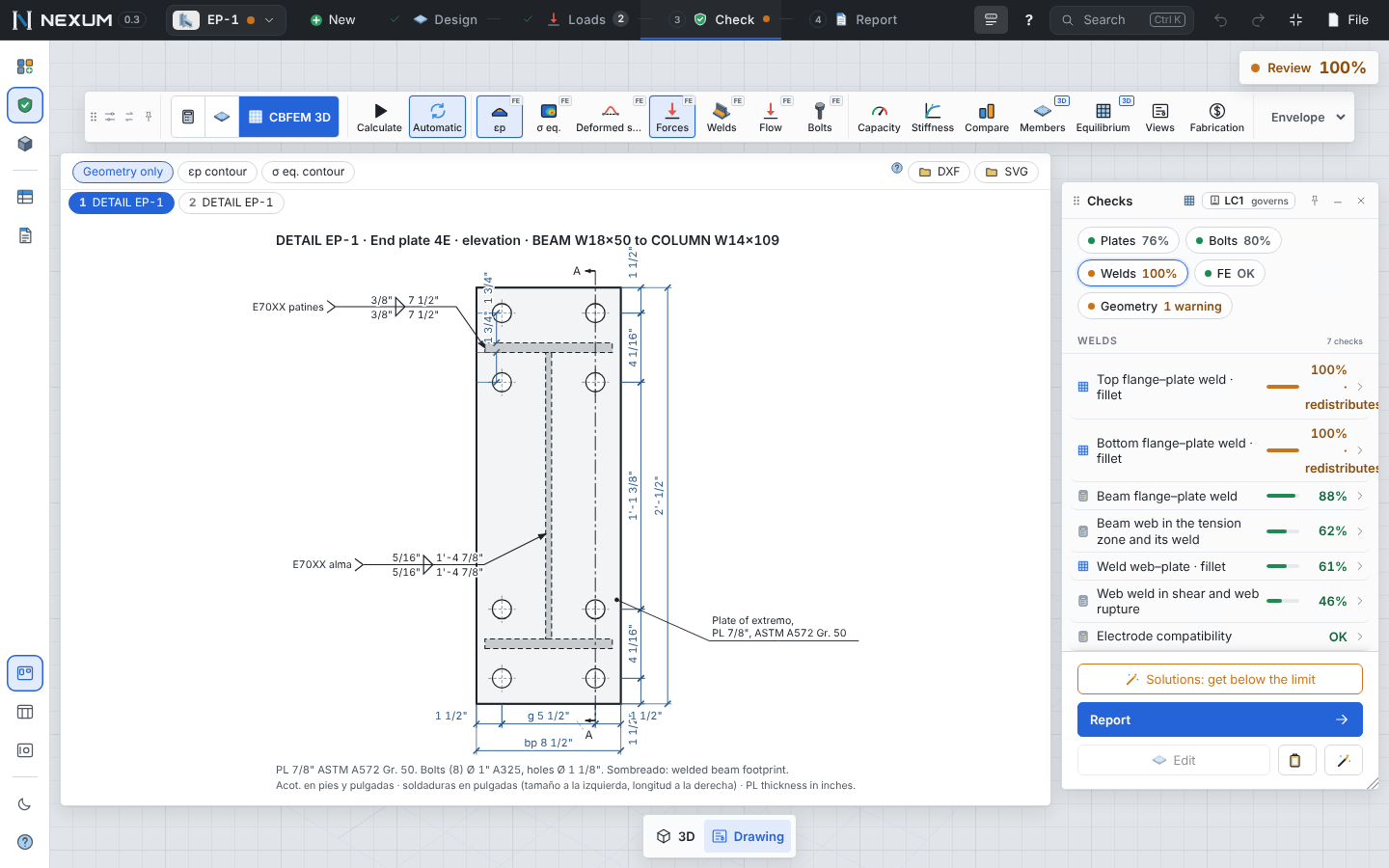
Switch the canvas to Drawing (bottom bar, or m=2d) for the dimensioned shop detail: plate with holes, welds with their AWS symbols, bolts and the part list. Export it from File → For the shop and the drafter: DXF (R12, CAD dimensions in mm, layers by element), SVG, PDF and the bill of materials (CSV for Excel).
What next#
- Try another connection type from the catalog.
- Run the whole project at once: connection selector ▾ → Dashboard → Calculate all, then Block report.
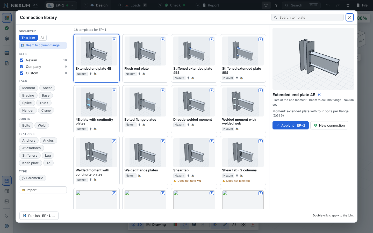
- Save your design as a template: connection selector ▾ → Save to my templates. It appears in New → My templates and in the library.