Loads and combinations
Nexum designs with factored loads (LRFD). Each connection has its own table of load cases; the forces depend on the connection type.
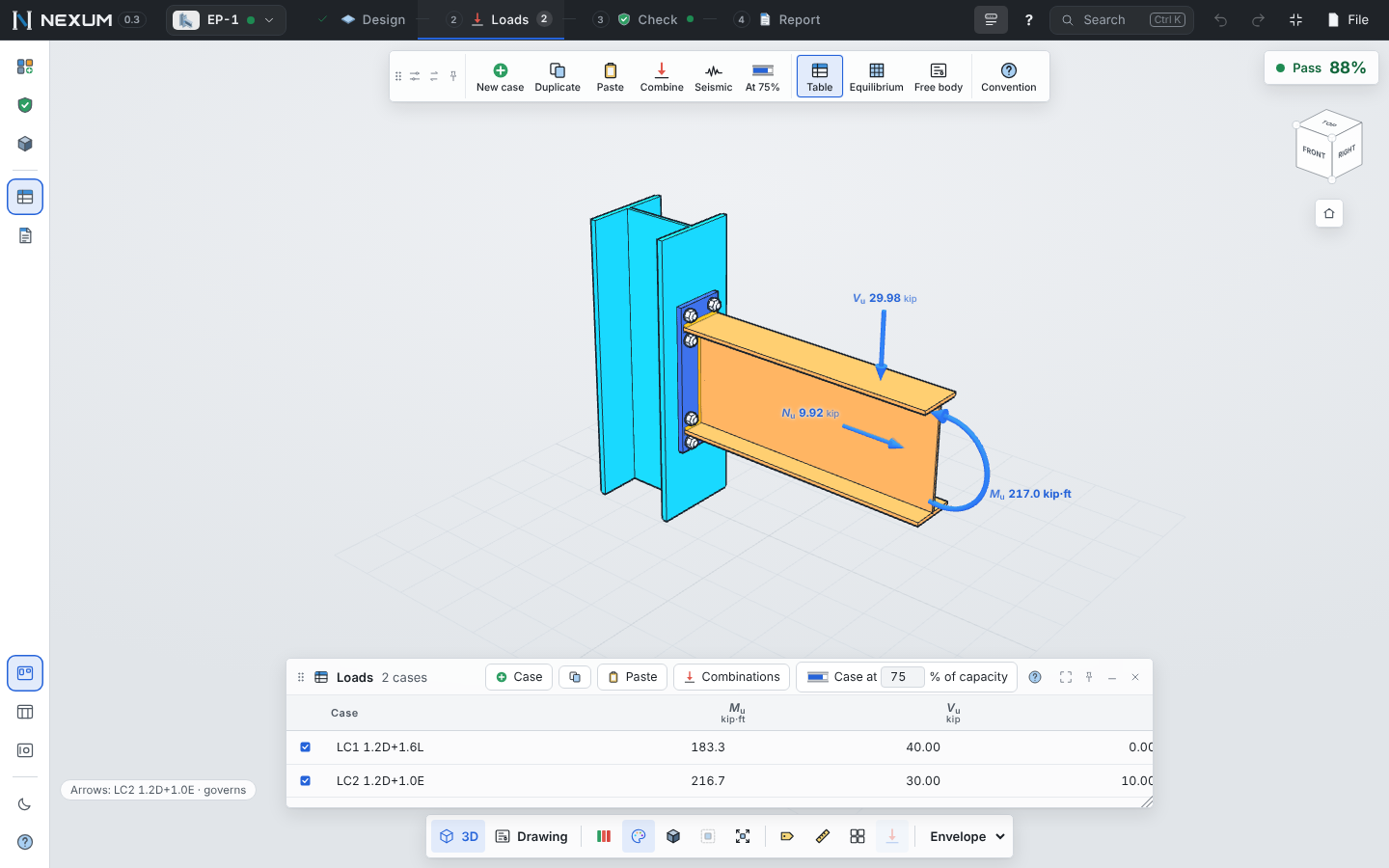
The load table#
Open Loads (Alt+2). The table opens in the Tools window and the arrows of the active case are drawn on the model.
- Columns are the forces this connection takes — for example Mu, Vu, Nu for a beam end, Pu, Vux, Vuy, Mux, Muy for a column base, P for a brace, Pc, P1…P6 for a truss joint. Each column header shows its symbol and unit; hover it for its meaning.
- Rows are load cases. Type the name you use in your analysis model (LC1 1.2D+1.6L).
- Edit like a spreadsheet: Tab and Enter move between cells, arrow keys too. Paste a block copied from Excel or from your analysis program; columns are matched in order.
- Checkbox — includes or excludes a case from the calculation (at least one stays on). Excluded cases are kept.
- ⚠ next to a value — the analytical method of this template does not take that force (for example the minor-axis moment in a base plate under DG1). The FE model still checks it.
- ⚡ and ƒ marks — with five or more cases, the FE model runs only on the cases that can govern (the worst of each analytical check and the two with the highest utilization): ⚡ marks them, ƒ marks cases checked only analytically.
Sign convention#
Click ? in the table header for the figure with the positive direction of each force. In short: axial forces are positive in tension, for members and braces alike; the figure shows the positive direction of every shear and moment of that connection type.
Case at a percentage of capacity#
Case at __ % of capacity (Loads toolbar) creates a case equal to a percentage of the member capacity (φMp, φVn or φPn, depending on the template) — useful to design a connection for a share of the member strength instead of the analysis forces.
Combinations#
Combinations builds the factored cases from service loads.
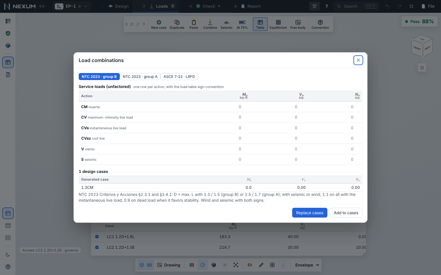
- Enter the service load of each action — dead, live (maximum), live (instantaneous), roof live, wind, seismic — in each column.
- Choose the code:
- ASCE 7-22 LRFD (§2.3.1 and §2.3.6, without Ev): 1.4D; 1.2D + 1.6L + 0.5Lr; 1.2D + 1.6Lr + (L or 0.5W); 1.2D + 1.0W + L + 0.5Lr; 1.2D + 1.0E + L; 0.9D + 1.0W; 0.9D + 1.0E.
- NTC 2023 (Mexico, Criterios y Acciones §2.3.1 and §3.4.1): 1.3CM + 1.5CV (group B) or 1.5 / 1.7 (group A) with the maximum live load; with seismic or wind, 1.1(CM + CVa ± S) with the instantaneous live load, and 0.9CM ± 1.1S when the dead load helps stability.
- The preview lists the design cases; Replace or Add writes them into the table (Ctrl+Z undoes it).
Wind and seismic enter with both signs. Only the combinations of actions that have a value are generated. The service loads stay with the connection so you can regenerate the cases later.
Seismic design (capacity design)#
Seismic (Loads toolbar, or the project settings) sets the seismic system of the project or of a connection — SMF/IMF/OMF, SCBF/OCBF, EBF, BRBF — per AISC 341-22. Nexum then generates read-only "Seismic ·" cases from the expected strength of the members (Ry·Fy, the required brace forces, the beam plastic moment at the column face…) and adds a Seismic group of checks (for example D2.6 for column bases, D2.5 for column splices, the brace connection requirements of F2 and F3). Where the Mexican NTC has an equivalent, it is noted in the check.
Loads from ETABS (members)#
For member design, ETABS in the Loads toolbar reads the Element Forces – Frames table pasted or as CSV, with the units of its units row. It creates one case per output case — each with its N/V/M diagram along the member — and can create one member per frame.