Member design
The Member template designs a rolled steel beam, column, beam-column, tie or brace from its internal forces, with AISC 360-16 (LRFD) and the tabulated properties of the AISC Shapes Database v15.0 (2,091 shapes). It is verified against 35 examples of the AISC Companion to the Manual (v15.1).
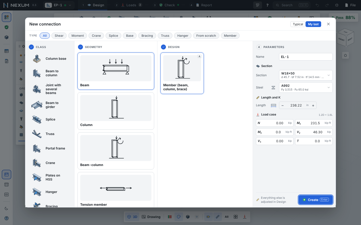
Create a member#
New (Alt+N) → Member, then Beam, Column, Beam-column, Tie or Brace. Or import a whole set from ETABS (below).
The interface shows only what applies to members: no bolts, welds, explode, FE method or fabrication.
Data#
| Data | Use |
|---|---|
| Shape | W, S, M, HP, C, MC, WT, MT, ST, L, 2L (spacing, LLBB/SLBB), rectangular and round HSS, Pipe |
| Steel | Fy and Fu from the catalog (round HSS A500 takes the round-tube Fy) |
| L, Kx, Ky, Kz | Length and effective length factors, with the pictograms of Table C-A-7.1 |
| Bracing by axis | Braced points along x (strong axis), y (weak axis), t (torsion), and the top and bottom flange for lateral-torsional buckling. Positive Mx uses the top-flange segments and negative Mx the bottom ones |
| Cb | From the moment diagram of each segment (Eq. F1-1) when the case has a diagram; otherwise the value you enter (1.0 is safe) |
| An/Ag, U | Tension rupture (D3, Table D3.1) |
| Single angle | E5 (connected leg, planar truss or box) and lateral-torsional restraint for F10 |
| Double angle | Intermediate connectors (E6) |
Forces per case: N (+ tension), Mx, My, Vy, Vx, T. They are taken as already amplified for second-order effects (direct analysis method, Chapter C, or Appendix 8).
Quick entry#
The Member tab of Tools opens by itself in Design:
- K with pictograms;
- a strip per axis with the braced points: click to add or remove one, ½ ⅓ ¼ to divide, copy from another axis;
- Lc and Lb with the Cb of each segment;
- the N / V / M diagrams and the utilization at each station.
Limit states#
| Chapter | What is checked |
|---|---|
| B4.1 | Classification of each element (nonslender / slender in compression; compact / noncompact / slender in flexure) |
| D2 | Tension yielding and rupture |
| E3–E7 | Flexural, torsional and flexural-torsional buckling; single angles (E5), built-up members (E6), slender elements (E7) |
| F2–F10 | Flexure about the major axis for every shape family, including lateral-torsional buckling, flange and web local buckling; single angles about the principal axes (F10) |
| F6 | Minor-axis flexure |
| G2–G6 | Shear in webs, HSS, round tubes and flanges |
| H1, H2 | Combined forces; for angles, H2 about the principal axes with the sign at points A, B, C |
| H1.3 | Doubly symmetric I-shapes in strong-axis flexure and compression: in-plane and out-of-plane checks; the less conservative of H1.1 and H1.3 governs |
| H3.1 | Torsion of HSS |
| H3.3 | Torsion of I-shapes with warping (Design Guide 9): twist solved along the member, warping and St. Venant stresses combined with axial and bending stresses |
| J10 | Concentrated force on a flange (load column Pc): flange local bending, web local yielding, web crippling, sidesway web buckling, web compression buckling |
| Ch. L | Deflection (optional, Deflection operation): total and live-load limits L/n; exact with service loads from Combine, approximate (factored case ÷ factor) without them |
| App. 6 | Required strength and stiffness of each point brace (columns and beams), shown as information for the bracing element |
Each check card shows the formula, the substitution and the result, as in connections.
From ETABS#
Loads → ETABS reads the Element Forces – Frames table (also Beam / Column / Brace Forces) pasted from ETABS or as a CSV, with the units of its units row.
- Apply to this member — one case per output case, each with its diagram along the member.
- Create one member per frame — opens the Members dashboard.
With a diagram, flexure is checked in each lateral-torsional segment with its own Lb and Cb, and the H1 (or H2) interaction at every station with its concurrent forces; the card says where it governs. Envelopes (Max/Min) are not concurrent — combining them in H1 is on the safe side, and Nexum says so.
Members dashboard#
Dashboard (in the Member panel, or the project dashboard → Members): one row per member with the ratio by type — axial, Mx, My, V·T, interaction — the abbreviation of what governs, the case, the capacities φPn, φMn, φVn, and export to CSV.
Cold-formed members (AISI S100-16)#
Pick a cold-formed shape in Shape and the same template designs it with AISI S100-16 (LRFD) instead of AISC 360:
- Shapes: SSMA lipped studs (
600S162-54) and tracks (600T125-54), AISI generic channels (9CS2.5x059), lipped zees (8ZS2.25x070), or any custom section typed asCF C 6x2x0.75x0.075(type C, U or Z; depth × flange × lip × thickness in inches; optionalR0.1875inside radius). - Steels: A653 SS Gr 33/50, A1003 ST33H/ST50H, A1011 SS Gr 36/50, HSLAS Gr 55.
- Properties are computed from the geometry (centerline with rounded corners), not taken from a table. They match the AISI Manual Table I-2 within 1% (A, rx, ry, xo, J).
- Checks: tension D2/D3; compression E2 (flexural, torsional, flexural-torsional), local buckling with the effective width method (E3.1, Appendix 1) and distortional buckling (E4 with Appendix 2 §2.3.3.3); strong-axis flexure F2 (lateral-torsional), F3.2.1 (effective section modulus at Fn) and F4 (distortional); weak-axis flexure; web shear G2.1; combined H1 and H2 at every station.
- Web crippling (G5) for lipped C and Z, fastened or not to the support, with Pc in the load table; combined with bending (H3). Matches published allowable web crippling tables to the pound.
- Web holes (operation Holes and sheathing): circular or non-circular, centered in the web; effective width per Appendix 1 (1.1.2, 1.1.3), shear reduction qs (G3) and web crippling reduction Rc (G6).
- Sheathing: rotational restraint kφ in distortional buckling, and the R-factor method (I6.2.1) for purlins with through-fastened panels under uplift.
- Back-to-back studs: type
2-600S162-54. Each stud takes half of the forces; compression uses the built-up section with the modified slenderness of I1.2 (set the number of intermediate connectors). - Deflection and Appendix 6 cards as for hot-rolled members.
Not yet covered for cold-formed: minor-axis distortional buckling (needs a finite strip analysis), boxed sections, web crippling of built-up I-sections and tracks.
Not yet covered#
Ponding (App. 2), fatigue (App. 3), composite members (Ch. I), torsion of channels, tees and angles, torsional bracing of beams (6.3.2b).